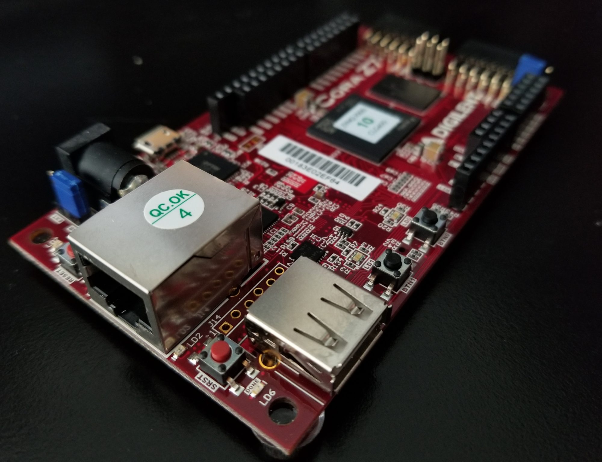
Before you can create and run a “Hello Cora” software project, the hardware on which to run the program needs to be built. This post goes through the creation of a simple single processor bare-metal (no OS) system on which the “Hello Cora” application will be executed.
Start Vivado either from a terminal or use the launcher.
Under “Quick Start” click “Create Project >”
Click “Next >”

Enter a project name and location. Check selection box to create a project subdirectory.

Click “Next >”
Select “RTL Project” and “Do not specify sources at this time”.

Click “Next >”
Select “Boards”. Under “Vendor:” choose “digilent.com”. In “Search:” type “Cora”. Select your Cora board.

Click “Next >”
Review the “New Project Summary”.

When satisfied click “Finish”.
The project is initialised and the “Project Manager” window appears.
In the flow navigator bar to the left click “Create Block Design”.

In the “Create Block Design Dialog”, give the design a name. Leave other entries as the default.

Click “OK”.
In the “Diagram” panel, click the “+” button to add IP. You may click the button in the middle of the panel or in the tool bar along its top edge.

In the search window begin typing “zy”. “ZYNQ7 Processing System” will appear.

Make sure that it is highlighted and hit the “Enter” key. A “processing_system_7_0” block will appear in the middle of the panel. You may need to zoom in to make it readable. “Zoom Fit” in the tool bar didn’t work for me. Left click and dragging a “Zoom Area” box around the IP block did. You can also hold “Ctrl” and the mouse wheel to zoom in and out.

Click “Run Block Automation” at the top of the panel.

Accept the defaults and click “OK”.
Zoom in again if necessary.

Right click in the “Diagram” tab and select “Validate Design”.

A clock pin has not been connected. We will fix this. Click “OK”.
On the diagram make a connection between “FCLK_CLK0” and “M_AXI_GP0_ACLK”. As you hover over “FCLK_CLK0” a pencil will appear. Click and hold on “FCLK_CLK0” and drag towards “M_ZXI_GP0_ACLK”. A green check will appear on the “M_ZXI_GP0_ACLK” pin. Drag to this pin and release the mouse button. A connection is established.

Again validate the design. Right click select “Validate Design” or press F6. Two warning messages appear.

These are not a problem. Refer to Hardware errata page of the Cora Z7 Reference Manual. Click “OK”.
Save your project. Click the “Sources” tab design Hierarchy.

Right click on “System (system.bd) (1), click “Create HDL Wrapper …”.

Select “Let Vivado manage wrapper and auto-update”. Click “OK”.
After updating a wrapper file will appear. In the “Flow Navigator” bar click “Generate Bitstream”.


Click “Yes” to launch synthesis and implementation.

Accept the defaults of the “Launch Runs” Dialog and click “OK”.
A progress bar will appear for a short time and then you will see progress updating in the upper right corner of the screen.

When complete the “Bitstream Generation Completed” dialog will appear.

Select “Open Implement Design” and click “OK”.
At this point I was asked to take a survey of Vivado 2018.3 experience. I selected “Remind me Later”. I will take the survey after a bit more experience with this release and bring up the zooming issue. Explore the device and/or the “Project Summary” tab.

At this point our hardware has been generated. Export the hardware description so that is can be imported into the SDK for software development. From the file menu select “File->Export->ExportHardware …”.

Select “Include bitstream” and export “<Local to Project>. Click “OK”.
A “HelloCora.SDK” folder will be created in the project directory. The hardware description file will be imported into the SDK in the next post. If your project needs saving, save it.
If continuing immediately on the the software part of the “Hello Cora” example, you can launch the SDK from the file menu and it will automatically load the hardware description file that you saved in the project. This used to crash in version 2016.4 under Ubuntu but appears to work fine in 2018.3. Nice! Thanks Xilinx.
